Capping
This tutorial explains, how to create cappings for clipplanes. A capping adds a solid surface to the cutting area of a clipplane by filling hollow spaces inside of parts. This makes it easier to distinguish between solid parts and true hollow spaces.
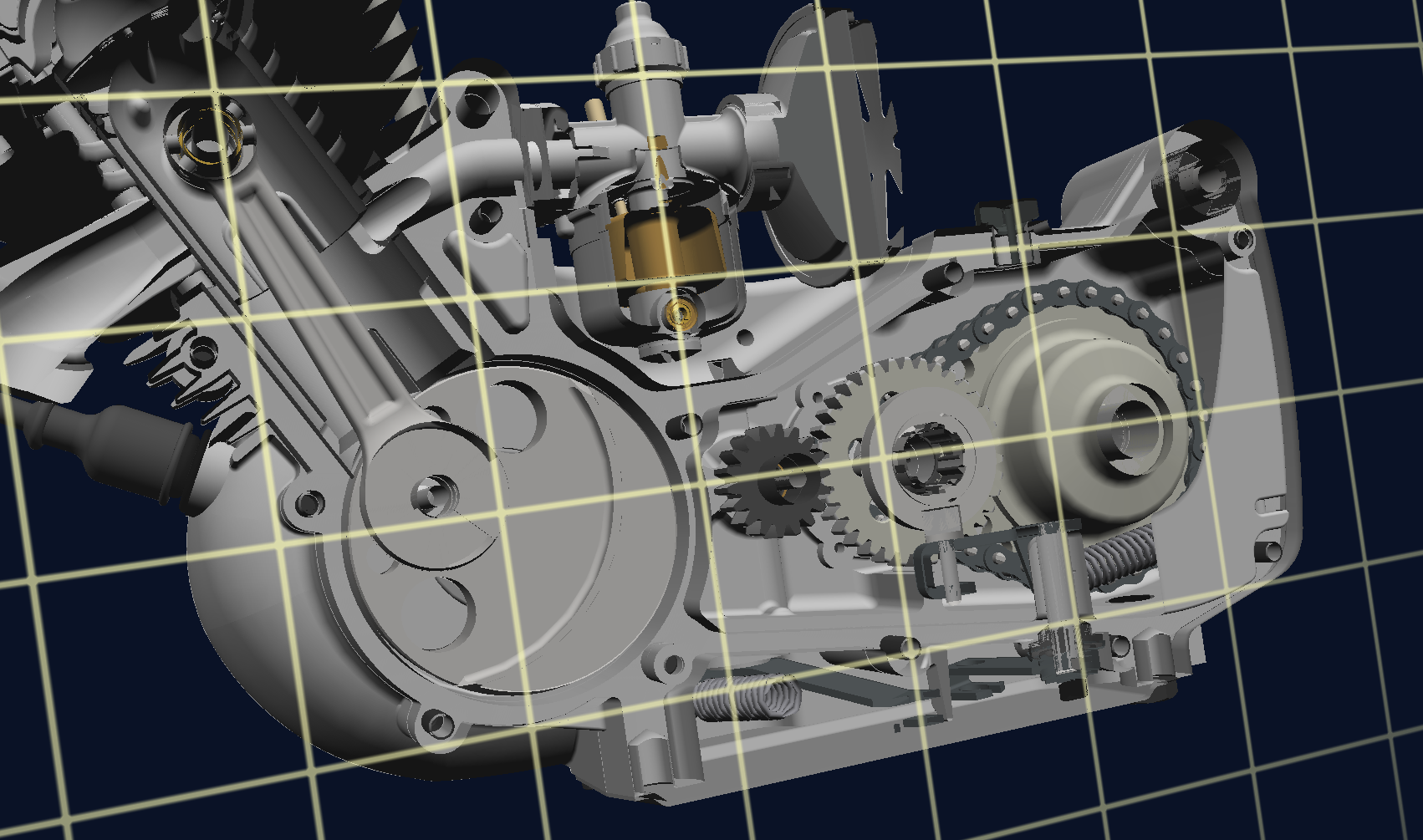
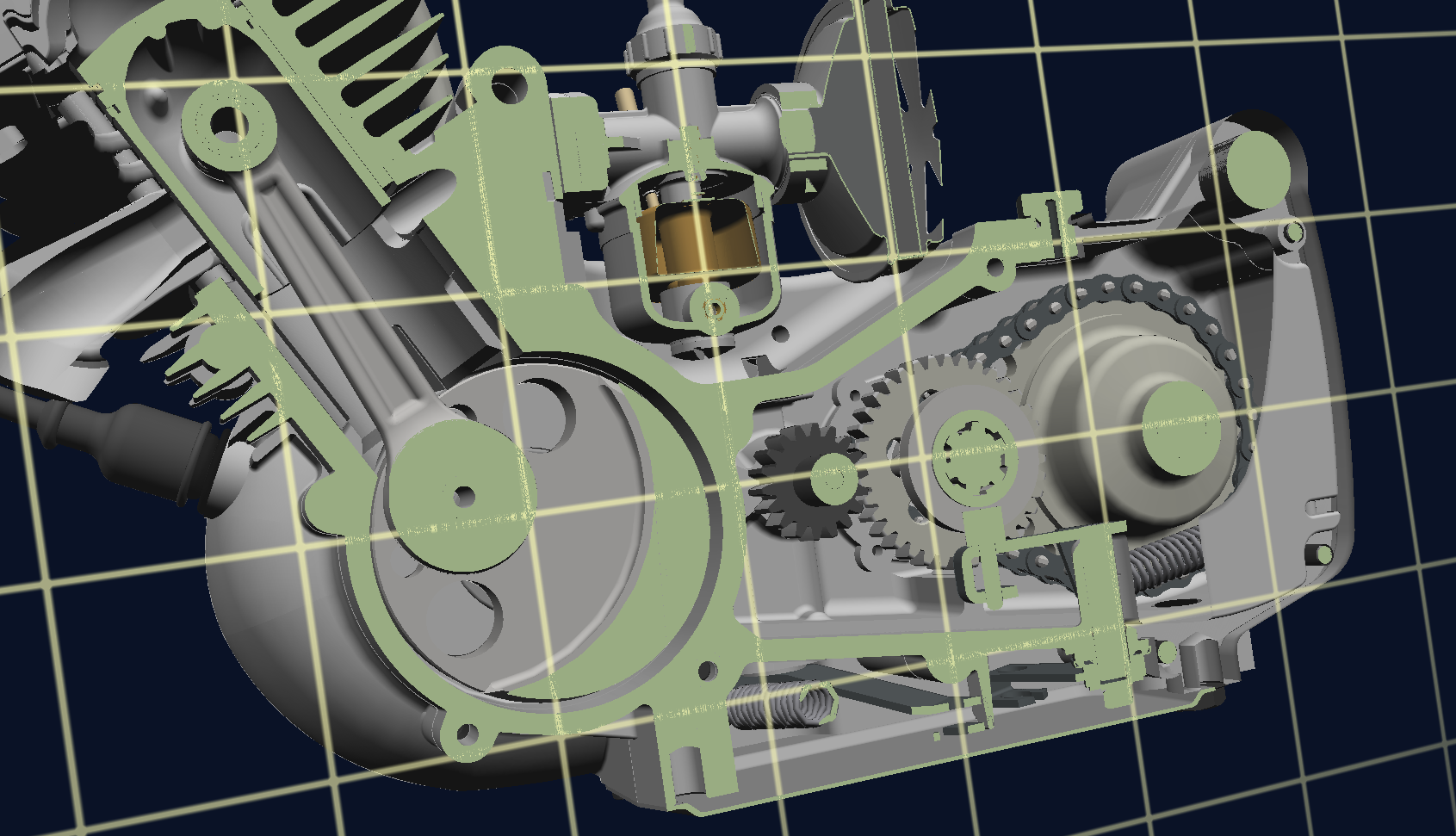
The picture below shows a engine without capping, followed by an image with a capping surface. Solid parts are clearly marked and better visible.
User Interface
The user interface provides the functionality to easily create capping. Therefore a clipplane must be created first. For more information about clipplanes, please refer to Clipplanes. The button for the capping creation is in the bottom right corner of the clipplane tab:
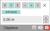
After pressing the button, the capping will be calculated. During this time, the icon changes to the following:
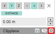
When the calculation is finished, the button is changed to this:
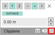
Pressing the button, will toggle the visibility of the capping. As long as the clipplane is not moved, no further calculation is needed.
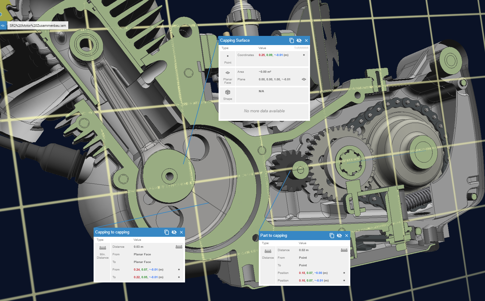
Measurement and Capping
Measurements can be also performed on capping surfaces. It can be applied to both between two capping surfaces or between one capping surface and a part of the model.
Using the API
To create capping by a script, please refer to ClipPlaneAPI.